

A mobile crane tip-over on a construction site does not look like an equipment malfunction. It looks like a controlled lift until the moment it does not. The sequence is predictable: a ground condition that was not assessed, an outrigger that was not fully extended, a load radius that was not checked against the load chart, or a combination of all three. The crane begins to tip when one of these conditions reaches its limit, and by that point the intervention window has closed.
OSHA’s crane and derrick standards at 29 CFR 1926 Subpart CC apply to cranes used in construction and represent the most comprehensive regulatory framework for crane setup and operation in the United States. They specify ground condition requirements, assembly and disassembly requirements, pre-shift inspection obligations, and operator qualification requirements that together define what a safe crane setup looks like from a legal and engineering standpoint.
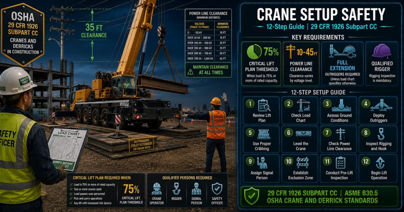
This guide covers the twelve steps that a compliant, safe crane setup requires under 29 CFR 1926 Subpart CC, from site assessment before the crane arrives to load path verification before the first lift.
This guide covers all twelve steps of a compliant crane setup under 29 CFR 1926 Subpart CC: pre-lift site assessment, ground bearing capacity verification, assembly and inspection under qualified supervision, outrigger deployment and load chart compliance, power line clearance, load weight verification, rigging inspection, lift plan preparation for critical lifts, pre-lift meeting requirements, signal person qualification, monitoring during operations, and disassembly and post-lift documentation.
Step 1: Conduct the Pre-Lift Site Assessment Before the Crane Arrives
The site assessment must be completed before the crane is mobilised, not on the day of the lift. Under 29 CFR 1926.1402, the employer must assess the site where the crane will be set up to determine whether the ground can support the crane and its load, whether power lines are within the equipment’s working radius, and whether the lift path is clear of obstructions that could interfere with the lift.
The site assessment must specifically identify:
- Ground composition, condition, and stability across the entire footprint of the crane including all outrigger positions
- The location of underground utilities, voids, basements, and drainage systems that could affect bearing capacity
- The location and voltage of all overhead power lines within the crane’s working radius
- The required lift radius and boom angle for each planned pick, compared against the crane’s load chart for that configuration
- Swing paths and boom travel routes that must remain clear during the lift
A site assessment conducted on the morning of the lift, after the crane has been mobilised, cannot change the crane selection or the site preparation that has already been committed to. The assessment becomes confirmatory rather than decision-making. Effective site assessments are completed at least several days before the lift so that site preparation, crane selection, and lift plan adjustments can be made based on the findings.
Step 2: Verify Ground Bearing Capacity for Outrigger Loads
Ground failure under outriggers is the leading cause of mobile crane tip-overs. Under 29 CFR 1926.1402(b), the employer must ensure that the ground can support the crane and its load, including the dynamic forces of crane operations. This requires knowing the maximum outrigger load for the planned configuration and comparing it against the bearing capacity of the ground at each outrigger position.
Ground bearing capacity is expressed in pounds per square foot (psf) or tonnes per square metre. Typical values range from approximately 500 psf for soft soil to over 4,000 psf for compact gravel or rock. Outrigger loads for large mobile cranes can exceed 200,000 pounds at a single pad. The engineer of record for the site or a qualified geotechnical engineer must confirm that the ground at each outrigger position can support the maximum outrigger load for the planned lift configuration.
Crane mats, timber cribbing, or steel outrigger pads are used to distribute outrigger loads over a larger bearing area when the ground bearing capacity does not match the outrigger point load. The mat or pad size must be calculated, not estimated, based on the actual outrigger load and the confirmed ground bearing capacity.
If the site’s geotechnical report does not specify bearing capacity at the outrigger locations, or if ground conditions have changed since the report was prepared (due to rain, excavation, or utility work), obtain an updated bearing capacity determination before the lift. A crane mat calculation based on an assumed bearing capacity that does not match actual site conditions provides no protection against ground failure.
Step 3: Ensure Assembly Is Supervised by a Qualified Person
Under 29 CFR 1926.1403, the assembly and disassembly of cranes must be directed by a qualified person who has the knowledge, training, and experience necessary to identify and resolve assembly-related hazards. For cranes with complex assembly procedures, the qualified person must be present during the entire assembly process, not available by phone.
The manufacturer’s assembly procedure, which is part of the crane’s load chart and operator manual, must be followed exactly. Deviations from the manufacturer’s assembly sequence, including installing boom sections in a different order, using non-manufacturer rigging for boom assembly, or omitting assembly steps to save time, create crane configurations that are not covered by the load chart and that the manufacturer has not validated for safety.
The qualified person requirement under 29 CFR 1926.1403 requires physical presence during assembly, not remote availability. A site superintendent who holds a qualification certificate but is managing another activity while the crane is being assembled does not satisfy the requirement. Assembly errors that cause crane failures during operation are frequently traced to assembly steps that were completed without qualified oversight.
Step 4: Complete the Pre-Shift Inspection Before Any Operation
Under 29 CFR 1926.1412(d), the crane operator must perform a pre-shift inspection before each shift in which the crane is used. The inspection must cover:
- Control systems and indicators for proper function
- Hydraulic system for leaks and proper fluid level
- Air system (where applicable) for pressure and leaks
- Hooks and hook latches for deformation, cracks, and latch function
- Wire rope for broken wires, kinks, crushing, and bird-caging
- Electrical and lighting systems
- Boom and jib sections for cracks, bends, and connection integrity
- Safety devices including anti-two-block warning systems and load moment indicators
Deficiencies identified during pre-shift inspection must be documented. The crane must not be operated if any deficiency that creates a safety hazard is found, until the deficiency is corrected and the crane is re-inspected.
Use a written pre-shift inspection checklist rather than relying on operator memory. The checklist must be signed by the operator and retained. OSHA inspectors reviewing a crane-related incident will request pre-shift inspection records as one of the first items. The absence of documented pre-shift inspections is itself a citable violation, separate from any safety deficiency that the inspection would have identified.
Step 5: Deploy Outriggers Fully and Verify Load Chart Applicability
Under 29 CFR 1926.1416(d)(1), outriggers must be fully extended unless the load chart specifically provides capacities for a partial extension configuration. Operating with partially extended outriggers using a full-extension load chart is one of the most dangerous and most commonly cited crane safety violations in construction.
Every load chart has a configuration page that specifies the outrigger extension, boom length, boom angle, and load radius for which the rated capacity applies. Before any lift, the operator must confirm that the crane’s actual configuration, including outrigger extension, matches the configuration for which the planned load is within capacity. If the actual lift radius is greater than the planned radius because of site conditions, the capacity at the actual radius must be recalculated from the load chart.
Load chart capacities are not interchangeable across configurations. A crane rated for 50 tons at 20-foot radius with full outriggers is not rated for 50 tons at 25-foot radius, or at 20-foot radius with partial outriggers. These are different configurations with different capacities, and the difference can be significant. Always verify the actual lift configuration against the load chart before the lift, not the configuration you planned for.
Step 6: Establish and Maintain Power Line Clearance
Contact with overhead power lines is the leading cause of crane-related fatalities in the United States. Under 29 CFR 1926.1408, cranes must maintain specific minimum clearance distances from power lines based on voltage:
- Up to 50 kV: minimum 10 feet clearance
- 50 kV to 200 kV: minimum 15 feet clearance
- 200 kV to 350 kV: minimum 20 feet clearance
- 350 kV to 500 kV: minimum 25 feet clearance
- 500 kV to 750 kV: minimum 35 feet clearance
- 750 kV to 1,000 kV: minimum 45 feet clearance
These clearances apply to all parts of the crane and its load, including the load line, hook block, and the load itself. If the voltage of a power line is unknown, the required clearance is 45 feet. These distances must be maintained throughout the entire swing arc and lift path, not only at the planned lift point.
Request de-energisation or physical relocation of power lines from the utility if the planned crane operation cannot maintain required clearance. This process can take days to weeks depending on the utility and the line type. Building this lead time into the project schedule before the lift date is determined prevents the situation where a lift must proceed in proximity to energised power lines because de-energisation was not requested in time.
Step 7: Verify Load Weight Before the Lift
Under 29 CFR 1926.1417, the operator must not make a lift if the weight of the load is unknown or if the load exceeds the crane’s rated capacity for the planned configuration. Load weight verification must use load cells, manufacturer data, engineering calculations, or certified weight documentation – not visual estimates or rule-of-thumb approximations.
The weight used for load chart verification must include the weight of all rigging equipment: hooks, shackles, slings, spreader bars, and any load-handling attachments. Rigging weight is frequently underestimated or omitted, particularly for heavy rigging configurations where the combined rigging weight can be several thousand pounds.
The crane’s load chart capacity covers the total suspended load including all rigging. A 40,000-pound structural steel piece in a rigging configuration with 2,000 pounds of slings, shackles, and spreader bars is a 42,000-pound lift, not a 40,000-pound lift. Every pound of rigging reduces the net capacity available for the load. Calculate the total suspended weight, including all rigging, and compare it to the load chart capacity for the planned configuration before the lift.
Step 8: Inspect All Rigging Before Attaching to the Load
Under 29 CFR 1926.1416(d)(4), all rigging equipment must be inspected before each use by a qualified rigger. Slings, shackles, hooks, spreader bars, and other load-handling devices must be inspected for damage including cuts, abrasions, broken wires, corrosion, deformation, and missing identification markings.
Rigging equipment must not be used beyond its rated capacity. The rated capacity of rigging equipment changes based on the angle of the sling legs: a sling rated for 10,000 pounds in a vertical configuration is rated for less than that when used in a two-leg configuration at an angle. ASME B30.9 provides the angle factor tables for sling capacity reduction, and riggers must apply these factors to every multi-leg sling configuration.
Rigging equipment with missing, illegible, or damaged identification tags must be removed from service. Under 29 CFR 1926.251, rigging equipment for material handling must be marked with its rated capacity. Equipment without a readable capacity marking has an unknown capacity and must not be used. Tag it OUT OF SERVICE and replace it before the lift.
Step 9: Prepare a Written Lift Plan for Critical Lifts
Under 29 CFR 1926.1431, a critical lift plan is required for any lift that exceeds 75 percent of the crane’s rated capacity or involves multiple cranes, lifting personnel, or hazardous materials. The critical lift plan must be prepared by a qualified person and must document: the weight of the load, the weight of all rigging, the crane configuration to be used, the load chart page and capacity for the configuration, the lift radius, the ground bearing capacity and mat calculations, and the emergency procedures if the lift encounters difficulties.
Even for non-critical lifts, a documented lift plan is a best practice that protects workers by ensuring that the lift parameters have been verified against the load chart before the operator begins the lift, not during it.
Critical lift plans must be completed and approved before the lift day, not during the pre-lift meeting. A plan that is being reviewed for the first time as the crew assembles for the lift is not a plan – it is a document. The purpose of the plan is to identify and resolve issues before the lift, which requires time between plan preparation and lift execution.
Step 10: Conduct the Pre-Lift Meeting With All Involved Personnel
Under 29 CFR 1926.1425, a pre-lift meeting must be held before each crane operation, attended by the operator, riggers, signal person, spotter (if used), and the competent or qualified person responsible for the lift. The meeting must cover:
- The lift plan, including load weight, lift radius, and crane configuration
- Ground conditions and any site-specific hazards
- Power line locations and clearance requirements
- Roles and responsibilities for each crew member
- Communication methods (hand signals or radio)
- Emergency stop procedures and evacuation routes
The pre-lift meeting is not a safety talk – it is an operational coordination meeting. Its purpose is to ensure that every person involved in the lift understands exactly what will happen, in what sequence, and what their specific role is at each stage.
Document the pre-lift meeting. Record the names of attendees, the date and time, and the key topics covered. If an incident occurs during the lift, the documentation of the pre-lift meeting demonstrates that the required coordination was completed and that participants were informed of their responsibilities. The absence of pre-lift meeting documentation contributes to enforcement exposure in any post-incident investigation.
Step 11: Verify Signal Person Qualification
Under 29 CFR 1926.1419, only qualified signal persons may give signals to crane operators. A qualified signal person must know and use the standard hand signals defined in ASME B30.5 (for mobile cranes) and must be qualified through either an accredited testing organisation or an employer-documented qualification process. The signal person must have a direct line of sight to the load or to the crane, and the operator must only respond to signals from the designated signal person except for an emergency stop signal, which any worker may give.
The use of improvised or non-standard hand signals is a documented cause of dropped loads and crane accidents. Signal confusion between an operator and an unqualified signal person has resulted in load movements in the wrong direction, unintended two-blocking, and swing collisions. All signals must be pre-established and understood by both the operator and the signal person before the lift begins.
On busy construction sites, it is common for any nearby worker to begin gesturing to a crane operator when a load needs to be positioned. Only the designated, qualified signal person may give movement signals to the crane operator. If the lift plan requires repositioning the signal person during the lift, the operator must stop all crane movement until the new signal arrangement is established and confirmed. There is no exception for brief or minor crane movements directed by unqualified workers.
Step 12: Monitor Setup Conditions and Document the Lift
Under 29 CFR 1926.1416, the operator must continuously monitor the crane’s operating conditions during the lift, including load line angle, load radius, and any changes in ground conditions or stability indicators. If the crane shows any signs of instability – including unusual sounds, unexpected movement, or any indication that the load has exceeded the rated capacity – the operator must stop the lift immediately and lower the load to a safe position before any assessment or corrective action is taken.
Post-lift documentation must include the pre-shift inspection record, the lift plan (for critical lifts), any deficiencies noted and corrective actions taken, and the pre-lift meeting attendance record. These records must be retained for the duration of the project and must be available for OSHA inspection upon request.
Assign a ground-level monitor whose sole responsibility during the lift is to observe ground conditions at each outrigger position and to watch for indicators of mat settlement, outrigger pad movement, or ground disturbance. This monitor has the authority to call a stop to the lift if any ground condition change is observed. Operators have limited visibility of outrigger conditions during a lift, and ground failure can develop faster than an operator can detect from the cab.
Knowledge Check
Test your understanding of crane setup requirements under 29 CFR 1926 Subpart CC.
No. Under 29 CFR 1926.1416(d)(1), outriggers must be fully extended unless the crane’s load chart specifically provides rated capacities for partial extension configurations. Using a full-extension load chart capacity for a 75 percent outrigger extension configuration means the crane is operating beyond its rated capacity for the actual configuration in use. If the load chart does not provide a capacity for 75 percent extension at the planned lift radius, the outriggers must be fully extended before any lift takes place.
No. Under 29 CFR 1926.1413(a)(2), wire rope must be removed from service if it has six randomly distributed broken wires in one rope lay, or three broken wires in one strand in one rope lay. Three broken wires in one rope lay meets the removal-from-service threshold. The rope must be replaced before the crane is operated. The operator must document the deficiency found during the pre-shift inspection and the corrective action taken before resuming operations.
Yes. Under 29 CFR 1926.1431, a critical lift plan is required when the lift exceeds 75 percent of the crane’s rated capacity for the configuration. At 38,000 pounds against a 42,000-pound capacity, the lift is at 90.5 percent of rated capacity, which exceeds the 75 percent threshold. The critical lift plan must be prepared by a qualified person and must be completed before the lift day. All elements required by 1926.1431 must be documented in the plan.
Crane Setup Compliance Checklist
✓ Site assessment completed before crane mobilisation, including ground bearing capacity, power line locations, and lift path clearance
✓ Ground bearing capacity verified at each outrigger position by a qualified geotechnical professional
✓ Crane assembly supervised by a qualified person who was physically present during assembly
✓ Pre-shift inspection completed, documented, and signed by operator before first lift
✓ Outriggers fully extended (or load chart verified for partial extension configuration if applicable)
✓ Required power line clearance distances confirmed for all boom positions and swing paths
✓ Load weight verified including all rigging components; total compared against load chart
✓ All rigging inspected by a qualified rigger and confirmed within rated capacity for sling angles used
✓ Critical lift plan completed and approved if lift exceeds 75 percent of rated capacity
✓ Pre-lift meeting conducted with all involved personnel; attendees documented
✓ Signal person confirmed as qualified under 29 CFR 1926.1419
✓ Ground monitor assigned with authority to stop the lift
Sources
- 29 CFR 1926 Subpart CC: Cranes and Derricks in Construction (1926.1400-1926.1442)
- 29 CFR 1926.1402: Ground Conditions
- 29 CFR 1926.1408: Power Line Safety (Kv and Clearance Distances)
- 29 CFR 1926.1431: Hoisting Personnel (Critical Lift Definitions and Requirements)
- ASME B30.5: Mobile and Locomotive Cranes (Signal Standards, Load Chart Requirements)